T Bias
In RF and microwave setups, it is often necessary to feed DC power onto a signal line without disrupting the measurement path. That is exactly where T Bias components are useful. They help combine DC bias and RF signals on the same transmission line, making them a practical choice for telecom labs, component testing, antenna systems, and general high-frequency measurement work.
On this page, buyers can explore T Bias options for different frequency ranges, connector formats, and DC handling requirements. Whether the priority is wideband testing, compact microwave integration, or higher current injection, choosing the right unit starts with understanding how the device fits into the RF chain.
How a T Bias works in an RF system
A bias tee is designed to combine DC power and RF signal through separate paths and then deliver them together on one port. Internally, the RF path and DC path are isolated so that RF energy is directed along the signal route while DC is injected without heavily affecting the intended frequency response.
This makes T Bias devices valuable in applications where active RF devices need biasing but the engineer also wants to preserve a controlled 50 Ohm signal path. In practice, they are commonly used in test benches, amplifier bias networks, antenna-related setups, and measurement systems where space and cable routing need to be simplified.
Typical applications for T Bias products
T Bias components are used across telecom, microwave, and electronic measurement environments. They are especially relevant when powering active devices through coaxial infrastructure, or when DC must be added to or removed from a line while maintaining signal continuity.
Depending on the setup, they may be used alongside other RF building blocks such as adapters for connector transitions or a power divider when distributing signals within a test or communication path. The exact system architecture varies, but the selection logic remains similar: match frequency coverage, connector interface, and DC capability to the real operating conditions.
What to check before selecting a T Bias
The first point is the frequency range. A low-frequency to GHz-range design may work well for general RF tasks, while millimeter-wave applications require much higher bandwidth and more specialized connector interfaces. It is also important to review insertion loss and VSWR because these affect signal integrity, especially in precision measurements.
The second point is DC handling. Voltage and current ratings should be aligned with the powered device, with enough margin for stable operation. Connector style also matters: SMA, N, 2.92 mm, and 1.85 mm versions suit different test environments, mechanical constraints, and frequency targets. In many systems, the right choice is not simply the widest bandwidth model, but the one that best matches the total RF and DC operating envelope.
Examples from Fairviewmicrowave and Tekbox
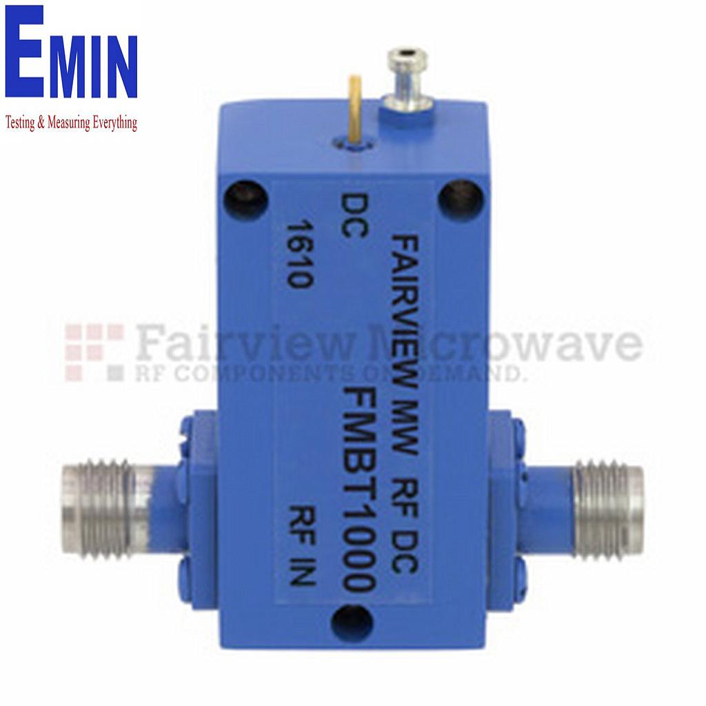
Products from Fairviewmicrowave cover a broad range of RF and microwave needs. For example, the Fairview SB6000A and Fairview FMBT1000 are relevant for common SMA-based lab configurations, while higher-frequency options such as the Fairview SB4000A, SB4030, SB65000A, and SB85000 extend into 2.92 mm and 1.85 mm interfaces for more demanding microwave work.
For applications where DC current capability is a stronger requirement, the Tekbox TBBT01 High Current Bias-Tee is a useful reference point. It supports operation from 5 kHz to 1.2 GHz and is intended for setups that need significantly higher current handling than many compact microwave bias tees. This type of product is often more relevant in EMC, RF power, or specialized bench environments where current delivery is as important as signal transmission.
Practical guidance for installation and use
Before making connections, confirm the port labeling and verify that the RF path, DC input, and combined output are used correctly. It is good practice to power down the setup first, then connect the RF instrument, DC source, and device under test in the proper sequence. This reduces the risk of accidental overvoltage, connector damage, or measurement errors caused by miswiring.
Cable quality and connector condition also have a direct impact on results. Even a capable T Bias can perform poorly if paired with worn coaxial assemblies or mismatched interfaces. If the test chain includes additional RF control components, engineers may also review related items such as telecommunication switches or isolating elements in the broader signal path to maintain repeatable measurements.
Common mistakes that affect RF performance
One of the most frequent issues is selecting a unit based only on frequency, while overlooking current limit, connector type, or allowable DC voltage. A model that fits the bandwidth but cannot safely support the required bias conditions may create instability or lead to premature failure.
Another common problem is assuming all bias tees are interchangeable. In reality, differences in connector family, return loss behavior, physical size, and current handling can be critical. High-frequency models such as the Fairview SB85000 are built for very wide bandwidth and compact microwave interfaces, while products like the Fairview SB3021 or SB4203 may be more suitable where N connectors and higher voltage capability are needed.
Choosing the right option for your lab or telecom setup
For general-purpose bench work, a compact SMA-based model is often a sensible starting point. If the setup moves into higher microwave frequencies, then 2.92 mm or 1.85 mm versions become more appropriate. If the challenge is delivering more DC current into the line, a high-current design should be prioritized over a smaller, broadband part.
A well-matched T Bias helps protect instruments, improve repeatability, and simplify RF system integration. By comparing operating bandwidth, connector format, and DC requirements carefully, engineers and procurement teams can narrow the selection to products that fit the real application instead of over-specifying or under-specifying the component.
For telecom and RF measurement work, T Bias components are small but important building blocks. The best choice usually comes from balancing signal performance, physical interface, and bias requirements so the device fits naturally into the complete test chain.
-
-
-
-
-
-
-
-
-
-
-
-
-
-
-
-
-
-
-
-
-
-
-
-